
Pulse Jet Valve Mistakes That Hurt Bag Filter Performance
Bag filter performance problems have a pattern. Differential pressure climbs. Filter bags are replaced earlier than expected. The compressed air system runs harder than it should. Stack emission readings drift toward the limit. And the maintenance team investigates – checking the filter bags, checking the compressed air supply, checking the controller settings – while the actual cause continues uncorrected in the valve specification that nobody reviewed carefully enough when the system was first commissioned or when valves were last replaced.
The pneumatic diaphragm valve is the component most directly responsible for the quality of the cleaning pulse in a reverse pulse jet dust collection system. Every filter bag row depends on its assigned valve to open fast, discharge maximum compressed air volume in the shortest possible time, and close cleanly. When the valve does this well, filter bags stay clean, differential pressure remains stable, and the system operates within emission limits day after day.
When it doesn’t – because of a specification decision made months or years earlier – the consequences spread across the entire filter system. And because the consequences are gradual rather than immediate, the root cause is rarely obvious by the time the problem is visible.
This article covers the valve selection mistakes that most frequently reduce bag filter performance in Indian industrial installations, why each mistake produces the consequences it does, and what the correct approach looks like in each case. If your dust collection system is underperforming and the cause isn’t obvious, there is a reasonable chance one or more of these mistakes is present in your current valve installation.
Why Pneumatic Diaphragm Valve Selection Affects Everything in a Bag Filter
Before addressing specific mistakes, it helps to understand why the pneumatic diaphragm valve sits so centrally in bag filter performance.
A reverse pulse jet bag filter cleans itself. Filter bags accumulate a dust cake on their outer surface – which, paradoxically, is beneficial up to a point, because a properly formed dust cake improves filtration efficiency by capturing finer particles. But beyond a certain cake thickness, the cake resistance becomes too high, differential pressure across the filter rises above the design range, airflow through the system reduces, and filtration effectiveness degrades.
The cleaning system’s job is to periodically dislodge this dust cake before it accumulates to the point of system performance degradation. A high-pressure compressed air pulse, delivered through the blow pipe and venturi nozzle into the filter bag, flexes the bag outward sharply – breaking the dust cake and allowing it to fall into the collection hopper.
The sharpness, volume, and consistency of that pulse is determined entirely by the pneumatic diaphragm valve. A valve that opens slowly rather than snapping open produces a gradual pressure rise rather than a sharp pulse – insufficient to properly flex the bag and break the cake. A valve that doesn’t fully open delivers reduced air volume per pulse. A valve that leaks between pulses bleeds compressed air continuously, reducing manifold pressure and affecting every subsequent pulse.
Each of these failure modes produces rising differential pressure – which looks identical from the differential pressure gauge whether the cause is the valve, the filter bags, the compressed air supply, or the controller settings. Identifying the valve as the source requires knowing what to look for.
Mistake 1: Selecting by Nominal Size Without Checking Flow Coefficient
This is the most technically consequential selection mistake, and also the most common. Engineers replacing a pneumatic diaphragm valve specify a replacement of the same nominal size – 2″, 1.5″, 1″ – from a different supplier, assume the performance will be equivalent, and move on.
It often isn’t.
The flow coefficient (Cv) of a valve determines how much compressed air volume passes through it at a given differential pressure in a given time. Two valves with the same nominal port size from different manufacturers can have significantly different Cv values – sometimes by a factor of 30% to 50% – because Cv depends on the internal flow geometry of the valve body, the diaphragm lift height, and the pilot orifice design. None of these are determined by the nominal port size.
What this means in practice: A replacement 2″ pneumatic diaphragm valve with a Cv of 9 installed in a position previously occupied by a valve with a Cv of 14 delivers approximately 36% less compressed air per pulse. The cleaning pulse is noticeably weaker. Bags in that row clean less thoroughly. Differential pressure across those bag rows rises progressively. Over weeks, the pattern spreads as the under-cleaned bags accumulate more cake between cycles.
The differential pressure gauge shows a rising trend. The maintenance investigation looks at everything except the valve specification change that happened three months earlier.
The correct approach: Always request the published Cv value from any diaphragm valve supplier before purchase. For replacement valves, compare the proposed replacement Cv against the original specification or the filter OEM’s design data. If the replacement Cv is lower, either source a different valve with the correct Cv or understand and accept the cleaning performance reduction you are introducing.
Reputable diaphragm valve manufacturers in India publish this specification as a standard part of product documentation. If a supplier cannot or will not provide it, treat that as a significant quality concern.
Mistake 2: Using Standard NBR Diaphragms in High-Temperature Applications
In standard industrial dust collection at ambient temperatures below 80°C, NBR (Nitrile Butadiene Rubber) is the appropriate diaphragm material – widely available, cost-effective, and resistant to the oils, fats, and general industrial dusts encountered in most applications.
Above 80°C continuous ambient temperature, NBR begins to harden. The material gradually loses the flexibility it needs to open and close with sufficient speed and completeness to deliver an effective cleaning pulse. A hardened diaphragm doesn’t fully lift from the seat – reducing the effective orifice area and therefore the Cv. It also loses the sealing compliance that prevents compressed air from leaking between pulses.
In Indian cement plant bag filters – particularly clinker cooler installations, kiln feed systems, and coal mill filters where ambient temperatures regularly exceed 80°C – standard NBR diaphragms frequently fail substantially earlier than their rated cycle life. The failure mode is progressive: gradual hardening, gradual pulse weakening, gradual differential pressure increase, until the diaphragm cracks or tears and the valve stops working altogether.
The same problem occurs in steel plant fume extraction zones, power plant boiler area filter installations, and any other high-ambient industrial application where the filter installation area is thermally demanding.
The correct approach: For any installation where ambient temperature regularly exceeds 80°C, specify high-temperature diaphragm compounds from the outset. High-temperature modified NBR, silicone-based compounds, or EPDM variants rated for the actual installation temperature are available from established diaphragm valves manufacturers in India. The cost difference over standard NBR is modest. The difference in service life in a high-temperature application is substantial.
When reviewing an installation that has experienced repeated premature diaphragm failures, always check the ambient temperature of the valve installation area before concluding the problem is material quality from the supplier. Material quality and material selection are different problems with different solutions.
Mistake 3: Incorrect Coil Voltage on Replacement Orders
This mistake is the most immediately obvious – a valve with the wrong coil voltage either destroys itself instantly (over-voltage) or doesn’t fire at all (under-voltage) – but it continues to occur with surprising regularity, particularly in plants where the original installation documentation is incomplete or unavailable.
The three common coil voltages in Indian industrial dust collection installations are 24V DC, 110V AC, and 230V AC. Of these, 230V AC is the most prevalent in systems designed to Indian domestic control standards, but 24V DC is increasingly common in modern PLC-based installations, and 110V AC appears in older equipment and in systems designed to British or American specification standards.
When a solenoid diaphragm valve fails and needs urgent replacement, the maintenance team sourcing the replacement often works from memory, from the original purchase order (which may specify the valve body size but not always the coil voltage), or from an assumption that the standard coil is appropriate for the installation. If the assumption is wrong, the replacement coil fails immediately on energisation (over-voltage) or the valve simply doesn’t fire (under-voltage) – generating a second maintenance call for a problem that was avoidable.
The correct approach: Before ordering any replacement diaphragm valve or coil, measure the output voltage at the controller terminal block for that valve position. This takes five minutes with a multimeter. Record the result in the maintenance log as part of the site valve register. For plants with multiple bag filter installations – possibly with different controller specifications for each – maintaining a valve register that records the coil voltage for each installation position eliminates this mistake permanently.
For new installations, the coil voltage is specified by the sequential timer controller output. Confirm this with the controller manufacturer before finalising the valve order.
Mistake 4: Specifying Inadequate IP Rating for the Installation Environment
The solenoid coil of a pneumatic diaphragm valve operates in the ambient environment of the filter installation – which, in Indian industrial facilities, typically involves elevated dust levels and, seasonally, significant humidity. The coil’s IP (Ingress Protection) rating determines its resistance to dust and moisture entering through the cable entry, the encapsulation seams, and the body joints.
A coil specified at IP54 in an environment that requires IP65 will experience progressive dust and moisture ingress. Initially, the coil operates normally. Over months, ingress accumulates. Coil insulation resistance degrades. Response becomes intermittent – sometimes the valve fires, sometimes it doesn’t. Eventually the coil fails entirely.
This failure mode is particularly common in:
- Cement plant filter installations where ambient dust levels in and around the bag filter housings are high even during normal operation
- Outdoor filter installations exposed to direct monsoon rainfall
- Filter rooms in coastal industrial facilities where salt-laden humidity is a year-round concern
- Steel plant filter areas where metallic particulate suspended in the ambient air is electrically conductive and accelerates insulation degradation
The failure is gradual and intermittent in its early stages – producing exactly the kind of inconsistent pulse behaviour that is difficult to diagnose without systematic valve testing.
The correct approach: Specify IP65 as the standard coil rating for all indoor Indian industrial dust collection installations in dusty environments. Specify IP67 for outdoor installations or areas exposed to direct rainfall or high-pressure washdown. The cost difference between IP54 and IP65 coils from any established diaphragm valve supplier is minimal. The cost of repeated coil failures caused by under-specified IP rating is not.
Mistake 5: Mixing Valve Brands or Specifications on the Same Manifold
Bag filter installations evolve over time. Valves are replaced individually as they fail rather than as a complete set. Different maintenance technicians order replacements from whichever supplier is convenient at the time. Over two or three years, the original uniform valve specification is replaced by a mixture of brands, generations, and specifications – all appearing physically compatible with the manifold but performing differently from each other.
The consequence is uneven cleaning across the filter. Rows equipped with higher-Cv valves receive more compressed air per pulse and clean more thoroughly than rows with lower-Cv valves. Rows with valves from brands whose diaphragm lift height differs from the original see different pulse duration characteristics even at the same controller on-time setting. Rows with any of the previous mistakes described in this article – wrong diaphragm material, marginal IP rating – degrade faster than others.
The result is a filter with some rows cleaned effectively and others progressively blinding. Differential pressure across the filter is uneven. Bag wear is uneven – bags in under-cleaned rows accumulate heavier cake between cycles, which accelerates wear. The filter system as a whole operates below its design specification, and the maintenance pattern – some bags replaced frequently, others lasting years – reflects the underlying variation in valve performance rather than any inherent property of the filter bags themselves.
The correct approach: Standardise on a single valve specification – ideally a single diaphragm valve manufacturer – for each filter installation. When individual valve replacements are required, source the same specification rather than whatever is available. Maintain a site valve register that records the correct specification for each manifold position. When a full valve set replacement is due, replace all valves simultaneously to reset the system to a uniform specification.
For plants managing multiple filter installations, standardising on a single valve supplier across the site simplifies procurement, reduces spare parts inventory complexity, and provides a consistent baseline for maintenance planning.
Mistake 6: Ignoring Thread Standard Compatibility
BSP (British Standard Pipe) and NPT (National Pipe Thread) are both common in Indian industrial installations. BSP appears in equipment designed to British and European standards and in many Indian-designed filter systems. NPT appears in equipment specified to American standards and in many imported filter systems from the United States and countries that follow American thread standards.
The thread forms look similar. The nominal sizes use the same naming convention – 1″, 1.5″, 2″. The threads engage when assembled. But the fundamental geometry differs: BSP parallel threads seal at the face with an O-ring or washer; NPT tapered threads seal on the thread flanks. A BSP valve assembled into an NPT manifold appears fitted but produces a joint that doesn’t seal correctly – resulting in compressed air leakage at the connection that reduces manifold pressure and affects pulse performance.
This mistake most often occurs during emergency replacement sourcing – when the priority is getting a valve on site quickly and the specification is taken from the physical size of the failed valve rather than from the thread standard recorded in the system documentation.
The correct approach: Record the thread standard for each manifold type on site in the valve register – not just the nominal size. When sourcing replacements, confirm thread standard as part of the specification. If thread standard is unclear, check the manifold connection against a thread gauge rather than assuming. The cost of a thread gauge is trivial; the cost of diagnosing intermittent compressed air losses from an incorrectly specified thread connection is not.
Mistake 7: Overlooking Compressed Air Quality Before Attributing Failure to the Valve
When pneumatic diaphragm valves fail repeatedly at intervals substantially shorter than their rated cycle life, the natural response is to question the valve quality – and sometimes to switch to a different diaphragm valve supplier or a different product range. In some cases, this is the right response. In many cases, it isn’t.
Premature diaphragm failure in Indian industrial dust collection installations is frequently caused by contaminated compressed air rather than by valve quality. Moisture and oil in the compressed air supply attack NBR diaphragms chemically and mechanically. Moisture causes swelling that reduces flexibility; oil causes swelling and surface degradation. Particulate contamination blocks the pilot orifice, causing sluggish or failed valve response. Any of these conditions can reduce diaphragm service life from the expected 1–3 years to months – with the failure appearing indistinguishable from a material quality problem.
Switching valve supplier without addressing the compressed air quality produces the same failure at the same interval from the new supplier. The valve quality is not the variable that determined the outcome.
The correct approach: Before concluding that premature diaphragm failure is a valve quality problem, inspect the coalescing filter bowl upstream of the manifold for moisture accumulation. Check the air dryer performance – an air dryer that is undersized, inadequately maintained, or bypassed is the most common cause of moisture in compressed air supplies to bag filter manifolds in Indian installations. Inspect the compressor oil separator if the system uses oil-injected compression.
A reputable solenoid diaphragm valve manufacturer will ask about compressed air quality when you report premature diaphragm failures, because they know this is the most likely explanation. A supplier who accepts the failure as normal and simply offers replacement parts without investigation is not providing the technical support that resolves the underlying problem.
Mistake 8: Buying on Diaphragm Valve Price Without Evaluating Total Cost of Ownership
The diaphragm valve price comparison that drives many procurement decisions is a unit price comparison – the cost of one valve body and coil assembly at the time of purchase. This is the wrong comparison to make for a component whose total cost of ownership over a five-year period is determined primarily by maintenance frequency, spare parts cost, and operational consequences of performance failure rather than by initial purchase price.
Consider two pneumatic diaphragm valves specified for the same installation:
Valve A: Lower unit price. Standard specification with unverified Cv. Limited technical support. Spare parts sourced on order with 3–4 week lead time. Diaphragm replacement required at 12-month intervals in this application.
Valve B: Higher unit price (15–20% more). Published Cv matching the system requirement. Technical support from an experienced diaphragm valves manufacturer. Domestic spare parts in stock, available within days. Diaphragm replacement required at 24-month intervals in the same application.
Over five years, Valve B requires two diaphragm replacements to Valve A’s four or five. The maintenance labour difference alone may exceed the initial purchase price difference. The operational consequences – differential pressure stability, filter bag life, emission compliance consistency – add further value that doesn’t appear in a unit price comparison.
For OEM manufacturers building dust collection equipment for their customers, the valve quality decision carries an additional dimension: a valve failure in a customer’s installation reflects on the OEM’s equipment and reputation. The indirect cost of a warranty call, a customer complaint, or an emergency site visit for a valve failure that a better specification would have prevented is not captured in the procurement price comparison.
The correct approach: When evaluating diaphragm valve price across multiple suppliers, calculate total cost of ownership over a realistic operating period – three to five years – incorporating the expected diaphragm replacement interval, spare parts cost, maintenance labour, and the value of operational stability. This comparison reliably produces different procurement decisions than a unit price comparison.
Mistake 9: Not Reviewing Controller Settings After Valve Replacement
The sequential timer controller settings – pulse duration and pulse interval – are configured for the valve and system specification that was in place at commissioning. When valves are replaced with a different specification (different Cv, different diaphragm material, different response characteristics), the controller settings may no longer be optimal for the new valve.
Pulse duration: If the replacement valve has a higher Cv than the original, the same pulse duration delivers more compressed air per pulse – which may be beneficial to cleaning performance but increases air consumption. If the replacement valve has a lower Cv, the same duration delivers less air – reducing cleaning effectiveness.
Pulse interval: If the replacement valve responds faster than the original, the manifold may recover pressure more quickly between pulses, potentially allowing the interval to be reduced without compromising cleaning quality. If response is slower, the existing interval may be too short for adequate manifold recovery.
Running the original controller settings after a valve specification change produces sub-optimal cleaning performance – sometimes better than before, sometimes worse, but rarely exactly right for the new valve. Yet controller settings are rarely reviewed after routine valve replacement.
The correct approach: After any valve replacement that involves a specification change – different manufacturer, different Cv, different diaphragm material – conduct a brief commissioning check. Monitor differential pressure during the cleaning cycle. Listen to the pulse quality from each valve. Verify manifold pressure recovery between pulses with a gauge. Adjust pulse duration and interval if the observed performance indicates the original settings are no longer optimal. Document the revised settings in the maintenance record.
Mistake 10: Sourcing From Traders Without Verifying the Manufacturing Chain
The Indian industrial valve market includes genuine diaphragm valve manufacturers, authorised distributors with documented supply relationships, and traders who supply unmarked or relabelled valves from unverified sources. The physical appearance of a valve from any of these supply chains can be similar – same nominal size, same apparent construction, same price range.
The quality differences are not visible externally. They appear in the diaphragm moulding precision, the valve body seat machining tolerances, the coil winding consistency, the accuracy of the stated Cv, and the batch-to-batch consistency of spare parts. Plants that have switched from a verified manufacturer to a lower-cost trader supply and then experienced premature valve failures frequently find that the failed valves have dimensional variations – diaphragm thickness inconsistency, seat geometry variation – that account for the performance difference.
For OEM manufacturers, sourcing from unverified traders creates a further problem: the absence of material traceability and quality documentation required for equipment qualification in regulated industries or for export market compliance.
The correct approach: Source from diaphragm valve manufacturers in India with documented manufacturing capability – own factory, quality control processes, and the ability to provide material certificates and dimensional inspection data on request. For high-volume OEM procurement, visit the manufacturing facility if practical. Request a sample batch inspection report before committing to a production volume.
A diaphragm valve supplier who cannot provide material traceability and who is reluctant to answer questions about their manufacturing process is not a suitable source for critical air pollution control components.
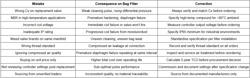
Quick Reference: Mistake, Consequence, and Correction
How to Audit Your Existing Pneumatic Diaphragm Valve Installation
If your bag filter is underperforming and the cause is unclear, this systematic audit will identify whether any of the above mistakes are present in your installation.
Step 1 – Gather the original specification. Locate the filter OEM drawings or original commissioning documentation. Identify the specified valve model, body size, Cv, diaphragm material, coil voltage, and IP rating. Compare this against what is currently installed.
Step 2 – Conduct a manual pulse test. Activate each valve in sequence manually from the controller. Listen to each pulse. Note any valves producing weak, delayed, or absent response – these are candidates for immediate inspection.
Step 3 – Inspect the compressed air supply. Check the coalescing filter bowl for moisture. If the bowl is wet, investigate the air dryer. Check upstream pipe work for moisture entry points. Resolve any air quality issues before replacing valves.
Step 4 – Inspect diaphragm condition. Remove the bonnet from any valve showing inconsistent pulse response. Inspect the diaphragm for hardening, cracking, swelling, thinning, or edge damage. Note which failure mode is present – this indicates the likely cause (temperature, contamination, fatigue, or material incompatibility).
Step 5 – Check manifold pressure. Install a pressure gauge at the manifold during a cleaning cycle. Verify that supply pressure is within the valve’s rated operating range and that pressure recovers adequately between pulses. If pressure recovery is slow, the pulse interval may be too short or the supply capacity may be insufficient.
Step 6 – Review the valve register. Confirm that all installed valves are the same specification – same Cv, same diaphragm material, same coil voltage, same manufacturer. If the register doesn’t exist, create one as part of the audit.
Step 7 – Review controller settings. Confirm that pulse duration and interval settings match the commissioned parameters. If they have been changed, document when and why. Consider whether the current settings are optimal for the installed valve specification.
Frequently Asked Questions
What is a pneumatic diaphragm valve in a dust collector?
A pneumatic diaphragm valve in a dust collector is the valve that controls the release of compressed air pulses used to clean filter bags in a reverse pulse jet bag filter system. A solenoid pilot responds to an electrical signal from the sequential timer controller, applying or venting compressed air to move the main diaphragm and release or stop the cleaning pulse. It is the component most directly responsible for the sharpness, volume, and consistency of the compressed air pulse that determines how effectively filter bags are cleaned and how stable the filter’s differential pressure remains during operation.
What is the flow coefficient (Cv) of a diaphragm valve and why does it matter?
The Cv of a diaphragm valve expresses its flow capacity – the volume of compressed air that passes through the valve at a given differential pressure. In pulse jet dust collection, a higher Cv means more compressed air volume per cleaning pulse, which means more effective bag cleaning. Two valves with the same nominal port size from different diaphragm valve manufacturers can have significantly different Cv values – sometimes differing by 30% to 50%. Always request and compare Cv data when evaluating valve suppliers, not nominal size alone.
Why do pneumatic diaphragm valves fail prematurely in cement plants?
The most common cause of premature diaphragm valve failure in cement plants is the use of standard NBR diaphragms in installation areas where ambient temperatures regularly exceed 80°C – particularly clinker cooler bag filters, kiln feed systems, and coal mill filter installations. Standard NBR hardens and loses flexibility at sustained temperatures above this threshold, producing progressively weaker cleaning pulses before the diaphragm cracks or tears. The correct specification for high-temperature cement plant locations is a high-temperature diaphragm compound rated for the actual ambient temperature of the installation.
How do I know if my bag filter is underperforming due to valve issues?
Signs that pneumatic diaphragm valve problems are affecting bag filter performance include: a rising trend in filter differential pressure during normal operation despite the cleaning system appearing to run; audibly weak or inconsistent pulses from one or more valve positions during a manual pulse test; filter bags in specific rows wearing faster than others or showing heavier dust accumulation on inspection; and compressed air consumption higher than expected for the filter size and cleaning frequency. A systematic valve-by-valve audit – pulse test, diaphragm inspection, Cv verification, and compressed air quality check – identifies the specific issue.
What is the difference between a solenoid diaphragm valve and a pneumatic diaphragm valve?
In the context of dust collection, a solenoid diaphragm valve refers to the complete assembly – a diaphragm valve body with an integral solenoid pilot that converts an electrical signal into pneumatic actuation of the main diaphragm. A pneumatic diaphragm valve is the broader category – any diaphragm valve actuated by compressed air, whether through a solenoid pilot (electrical control) or a direct pneumatic signal (for use in hazardous area or pneumatic-only control systems). In most Indian industrial bag filter installations, solenoid diaphragm valves are the standard – they interface directly with sequential timer controllers for automated pulse jet cleaning.
How much does a diaphragm valve cost in India and what drives the price?
Diaphragm valve price in India varies with body size, diaphragm material, solenoid coil specification, IP rating, and whether the valve includes a tank-mounted or manifold-mounted configuration. Standard industrial solenoid diaphragm valves for dust collection applications range from a few hundred to several thousand rupees per unit depending on specification. For procurement decisions, total cost of ownership – incorporating expected diaphragm replacement frequency, spare parts cost, domestic availability, and the operational value of consistent filter performance – is a more reliable basis for supplier comparison than unit price alone. A valve priced 20% below market that requires diaphragm replacement at half the standard interval costs more over a three-year operating period.
Which diaphragm valve manufacturers in India should I consider for industrial dust collection?
When evaluating diaphragm valve manufacturers in India, prioritise companies with: own manufacturing facilities rather than assembly or trading operations; published flow coefficient (Cv) data for their valve range; multiple diaphragm material options including high-temperature compounds; domestic stock of replacement diaphragm kits with short delivery times; application engineering support specifically for dust collection systems; and documented experience across multiple industrial sectors including cement, steel, power, and pharmaceuticals. For critical air pollution control applications, the manufacturing depth and spare parts support behind the valve are as important as the valve specification itself.
How often should pneumatic diaphragm valves be replaced in an industrial bag filter?
Diaphragm replacement – rather than complete valve replacement – is the standard maintenance event. In standard industrial duty with clean compressed air and correct diaphragm material specification, annual inspection with replacement as needed is appropriate. In high-cycle continuous-duty applications, planned replacement every 8–12 months prevents unplanned failures. Complete valve body replacement is only required when the valve body seat is damaged or the body itself fails – which should be infrequent with quality valves from established diaphragm valve manufacturers. Maintaining a spare diaphragm kit inventory on site for each installed valve size enables immediate response to unexpected failures.
Conclusion
Every mistake covered in this article is avoidable. None requires exceptional engineering knowledge to prevent – just the right information applied at the specification stage, and a valve supplier relationship that supports good decisions rather than simply fulfilling purchase orders.
The pneumatic diaphragm valve at the centre of a bag filter cleaning system is a precision component working in demanding conditions, cycling millions of times per year in environments that range from abrasive and dusty to corrosive and thermally challenging. Getting its specification right – body size and Cv matched to the system, diaphragm material matched to the process conditions, coil voltage and IP rating matched to the installation environment, sourced from a manufacturer whose quality is verifiable – is the foundation of a bag filter system that performs reliably and stays within emission limits without requiring constant maintenance attention.
The total cost of avoiding these mistakes is a more careful specification process. The total cost of not avoiding them is measured in maintenance logs, filter bag replacements, compressed air waste, and, in regulated industries, emission compliance incidents that have consequences well beyond the filter room.
Want to make sure your dust collector pulse valves are correctly specified from the start?
Maniks has manufactured tank mounted valves, pilot operated diaphragm valves, solenoid diaphragm valve assemblies, and complete dust collector pulse valve solutions for over 47 years. Our engineering team works with plant engineers, maintenance managers, and OEM manufacturers across India to identify the right valve specification for each application – and to support installations with genuine domestic spare parts availability and technical guidance when it’s needed.
If your bag filter system is underperforming and you suspect the valves are part of the problem, our team can review your current installation specification and provide recommendations. If you’re specifying valves for a new installation, we’ll make sure the specification is right before the order is placed.
Explore our Tank Mounted Valves and Diaphragm Valve Solutions or contact us to discuss your application and request a technical consultation.