
Pulse Jet Solenoid Valves for High-Cycle Dust Collectors
In a cement plant running three shifts, or a steel mill where the electric arc furnace runs continuously, the bag filter system never really stops. And neither do the pulse jet solenoid valves driving it.
Every few seconds, these valves snap open and closed – firing compressed air through blow pipes to clean rows of filter bags. In a high-cycle installation, a single valve may complete 5 to 10 million cycles per year. At that rate, a valve that wasn’t designed for continuous duty won’t last a maintenance interval.
This guide covers everything you need to know about selecting, maintaining, and getting maximum service life from pulse jet solenoid valves in demanding, high-cycle industrial applications – from what separates a capable valve from a failure waiting to happen, to the specification details that actually matter on the plant floor.
What Is a Pulse Jet Solenoid Valve, and Why Is It Central to Dust Collection?
A pulse jet solenoid valve is the electrically actuated valve that controls the release of high-pressure compressed air bursts used to clean fabric filter bags in a reverse pulse jet dust collection system. It opens for a fraction of a second – typically 50 to 150 milliseconds – releasing a powerful blast of air that travels through the blow pipe, enters the filter bag via a venturi nozzle, and flexes the bag outward to dislodge accumulated dust cake.
The dust drops into the collection hopper below, and the filter bag returns to filtration duty – all without interrupting the airflow through the system.
In most industrial bag filter installations, you’ll have anywhere from a few valves to several dozen, each responsible for cleaning one row of filter bags. The sequential timer controller sequences through each valve in turn, ensuring systematic, consistent cleaning across the entire filter area.
Get the valve selection right, and the system runs quietly, efficiently, and with minimal intervention for years. Get it wrong, and you face rising differential pressure, blinded bags, frequent diaphragm failures, and the kind of unplanned downtime that engineers spend careers trying to avoid.
Why High-Cycle Applications Demand a Different Standard
Not all dust collector installations put the same demand on a pulse valve. A woodworking shop running one shift per day is a fundamentally different operating environment from a cement clinker cooler running around the clock.
In high-cycle applications, the key variables that separate acceptable valves from exceptional ones are:
Cycle frequency and total cycle count. A valve rated for 1 million cycles will fail in months on an installation that demands 5 million cycles per year. Always match the valve’s tested cycle life rating to your actual system’s cleaning frequency.
Compressed air quality. Moisture and oil contamination attack the diaphragm from the inside, while particulates block the solenoid pilot passage and cause sluggish or failed response. In continuous-duty installations, upstream air treatment – a coalescing filter and air dryer minimum – is not optional.
Ambient temperature. Cement kilns, power plant boiler areas, and steel mill environments can expose equipment to sustained high temperatures. Valve body materials, diaphragm compounds, and solenoid coil insulation class must be specified for the actual thermal environment.
Pulse duration and interval settings. Running pulse durations too long stresses the diaphragm unnecessarily. Running intervals too short doesn’t allow adequate pressure recovery in the manifold between pulses. Both increase valve wear in ways that shorten service life in high-cycle conditions.
A pulse solenoid valve designed specifically for industrial continuous duty addresses all of these factors – in the material specification, in the diaphragm geometry, in the coil construction, and in the pilot passage design.
Types of Pulse Valves Used in Industrial Dust Collectors
Pilot Operated Pulse Valves
The pilot operated valve is the dominant design in industrial bag filter applications. A small solenoid pilot controls a pressure chamber behind the main diaphragm. When the pilot opens, it vents the back-pressure, the diaphragm lifts, and compressed air flows through the main valve body at high volume and velocity.
Because the solenoid only moves the pilot – not the main valve – it requires relatively low electrical power while still delivering the high-flow performance needed to clean large filter bag areas. This makes pilot operated valves efficient and reliable for continuous duty.
For high-cycle installations, the pilot passage design matters significantly. A pilot with adequate orifice sizing and a clean, particle-free air supply will respond consistently cycle after cycle. A partially blocked pilot causes delayed or partial valve opening, which leads to inadequate bag cleaning – and an apparent “valve problem” that’s actually an air quality problem.
Direct-Acting Solenoid Valves
Direct-acting designs move the valve seat directly by electromagnetic force, without a pilot. They respond faster and work reliably at lower differential pressures, which suits smaller filter systems and applications where compressed air supply pressure fluctuates.
Their limitation in high-cycle industrial use is flow capacity – the electromagnetic force available limits how large the main orifice can be, which constrains the volume of air per pulse. For large bag filter compartments with multiple bags per row, pilot operated valves remain the preferred choice.
Single-Body vs. In-Line Valve Configurations
Single-body valves mount directly to the compressed air manifold and discharge directly into the blow pipe. In-line configurations connect via threaded or flanged fittings. The correct configuration depends on the manifold design of your specific dust collector – and compatibility should be verified against OEM drawings before procurement.
Selecting the Right Pulse Jet Valve for Your System
Selecting the right pulse valve for a dust collector isn’t complicated, but it requires knowing the right parameters. Here’s what to specify:
Body Size
Common sizes are 1″ (DN25), 1.5″ (DN40), 2″ (DN50), and 2.5″ (DN65). The correct size matches your manifold port dimensions and provides the compressed air flow volume needed to clean the number of filter bags in each row.
Undersized valves can’t deliver enough air volume per pulse, leaving bags partially cleaned. Oversized valves on small manifolds may cause excessive pressure drop across the system. Match the valve size to the filter OEM’s specification wherever possible.
Operating Pressure
Most reverse pulse jet dust collection systems operate between 5 and 7 bar (70–100 PSI). Some high-particulate-loading applications use pressures up to 8 bar. Confirm the valve’s rated operating pressure range – both minimum and maximum – against your system’s actual supply pressure.
Coil Voltage
Solenoid coils are wound for specific voltages: 24V DC, 110V AC, and 220V AC are the most widely used in Indian and export installations. Incorrect voltage is the single most common cause of immediate coil failure during commissioning. Verify the voltage output of your sequential timer controller before ordering.
Diaphragm Material
- NBR (Nitrile Butadiene Rubber): Standard for most industrial applications. Good resistance to oils, moderate temperatures, and general particulate environments.
- PTFE-coated NBR: Adds chemical resistance and reduces particulate adhesion. Suited to chemical plant applications and mildly corrosive process gases.
- Full PTFE or EPDM: Required for aggressive chemical exposure or sustained high-temperature applications such as cement kiln filter installations.
In high-cycle systems, diaphragm material selection directly affects service life. The right material for the application can double the maintenance interval compared to a generic specification.
IP Rating
For dusty, wet, or outdoor industrial environments, specify IP65 as the minimum for the solenoid coil enclosure. Applications near washdown areas or exposed to rainfall require IP67. Coil failures in industrial environments are frequently caused by moisture ingress in under-rated enclosures.
Cycle Life Rating
Ask the manufacturer for tested cycle life data. A quality industrial pulse valve should be rated and tested to several million cycles. For high-cycle applications, prioritise this specification over initial cost – the total cost of ownership over a 3-to-5-year period will be determined far more by service interval than by purchase price.
High-Cycle Application Reference: Industry by Industry
Cement Manufacturing
Cement plants are among the most demanding environments for dust collector pulse valves. Kiln feed systems, clinker coolers, coal mills, and cement grinding circuits all generate heavy particulate loads. Filter systems run continuously, cleaning cycles are frequent, and ambient temperatures in many installation areas are elevated.
Valves in cement plant applications should be specified with high-temperature rated diaphragms, IP65 or better coils, and regular diaphragm inspection on a 12-month cycle. Compressed air quality is particularly critical – cement dust is abrasive, and any particulate contamination in the air supply will accelerate pilot passage wear.
Steel Mills and Foundries
Electric arc furnace fume extraction, cupola furnace filters, and shot blasting dust collectors in steel and foundry environments put valves through high particulate loads and frequent cleaning cycles. Metallic and abrasive dust puts additional wear on diaphragms if air quality is not controlled.
In these installations, oversizing the compressed air treatment system is rarely a mistake. A well-maintained coalescing filter and refrigerant dryer upstream of the manifold consistently extends valve service life in high-cycle foundry applications.
Power Plants
Coal handling and conveying systems, coal mill vents, and fly ash silo venting involve fine, abrasive dust that penetrates mechanical components aggressively. Power plant bag filters often run continuously, with online pulse jet cleaning to maintain filter differential pressure without interrupting boiler operation.
For these installations, valves should be specified for continuous duty, with consideration for pulse frequency optimisation – working with the controller settings to find the minimum cleaning frequency that maintains acceptable differential pressure, rather than running the system at maximum cleaning rate unnecessarily.
Pharmaceutical and Food Processing
These industries require clean-room compatible materials and consistent, validated performance. Diaphragm materials must be food-grade or pharmaceutical-grade where filter bags handle product contact air streams. Consistent valve response time – valve-to-valve – is important for uniform filter cleaning in these applications.
Chemicals and Textiles
Chemical plant powder handling systems may involve process gases that attack standard diaphragm materials. Confirming diaphragm compatibility with the specific chemical environment is essential before specification. Textile applications – fibre dust from carding, spinning, and weaving – tend to create high-volume, lighter-particulate-load conditions where valve reliability over long intervals matters more than extreme cycle life.
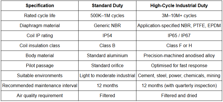
Specification Comparison: Standard vs. High-Cycle Duty Pulse Valves
Maintenance Best Practices for High-Cycle Installations
The maintenance discipline around pulse valves in continuous-duty applications makes the difference between a system that runs reliably for five years and one that requires constant intervention.
- Quarterly inspection: Listen to each valve firing during a manual pulse test. A healthy valve produces a sharp, consistent crack. A weak or muffled pulse indicates a diaphragm starting to fail or a partially blocked pilot. Identifying this at a quarterly inspection prevents an emergency during a production run.
- Annual diaphragm replacement: In high-cycle applications – more than 3 million cycles per year – schedule diaphragm replacement annually as a preventive measure rather than waiting for failure. The cost of a planned diaphragm replacement during a scheduled shutdown is a fraction of the cost of an unplanned production stoppage.
- Monitor differential pressure trends: A rising trend in bag filter differential pressure during normal operation – even though the cleaning system is running – signals that cleaning effectiveness has degraded. This is frequently the first sign that several valves are underperforming before individual valve failure becomes obvious.
- Maintain a site spare kit: Stock at minimum one full diaphragm replacement kit per valve size installed on site. This enables immediate corrective maintenance without waiting for procurement lead times.
- Check and log controller settings: Pulse duration, interval, and cleaning sequence should be documented and compared against the original design parameters. Creeping adjustments made over time – often by well-intentioned maintenance staff trying to address symptoms rather than causes – can result in settings that stress valves unnecessarily or leave bags under-cleaned.
- Inspect the air treatment system: At every planned maintenance interval, inspect the coalescing filter bowl for moisture accumulation and the drain function. Saturated filter elements downstream of an inadequate air dryer are among the most common root causes of premature diaphragm failure in high-cycle installations.
Common Mistakes That Shorten Valve Life in High-Cycle Systems
- Skipping compressed air quality. Moisture and oil contamination are the most reliable ways to shorten diaphragm life. A simple refrigerant dryer and coalescing filter upstream of the pulse valve manifold pays for itself repeatedly in extended valve service life.
- Setting pulse duration too long. A pulse duration of 100ms is not better than 60ms if 60ms is sufficient to clean the bags. Longer pulses cause unnecessary diaphragm flex cycles and increase air consumption without improving cleaning performance.
- Mixing valve brands mid-system. Different manufacturers’ valves have different flow characteristics and diaphragm geometries. Mixing brands on the same manifold can result in uneven cleaning across filter rows, with some rows receiving more air volume per pulse than others.
- Replacing valves without investigating root cause. If a diaphragm failed in eight months on a system where it should last two years, replacing it with an identical diaphragm without addressing the underlying cause – contaminated air, excessive pulse frequency, wrong voltage – guarantees the same failure.
- Procuring on price alone. For light-duty applications, a basic valve specification may be adequate. For high-cycle continuous-duty installations, a valve rated and tested for the actual operating conditions will cost less over a five-year ownership period than a cheaper valve replaced twice as often.
Industry Best Practices for Pulse Jet System Performance
- Commission with compressed air. Before final commissioning, flush the manifold and blow pipe system with compressed air to remove debris from installation. Debris in the manifold is a frequent cause of pilot blockage failures on new installations.
- Set the right cleaning mode for the application. Online cleaning – continuous pulse jet cleaning while the filter remains in service – suits continuous process industries where shutdown isn’t practical. Offline cleaning, which isolates one compartment at a time before pulsing, is more thorough for applications where a brief filter compartment shutdown is acceptable. The valve specification and controller settings differ between these modes.
- Sequence cleaning to allow hopper clearance. In systems without positive hopper discharge, cleaning too aggressively – sequencing through valves too rapidly – can re-entrain settled dust before it reaches the hopper. Set the inter-valve interval to allow adequate settling time.
- Document baseline performance. At commissioning or after a major maintenance event, record the differential pressure at various airflow rates under normal conditions. This baseline makes it far easier to identify performance degradation in later months.
- Involve the valve manufacturer in application review. For new installations or system upgrades, a valve manufacturer with genuine dust collection application experience can identify potential issues – manifold sizing, air supply capacity, controller configuration – before they become operational problems.
Frequently Asked Questions
What is a pulse jet solenoid valve?
A pulse jet solenoid valve is an electrically actuated valve used in reverse pulse jet dust collection systems to release short, powerful bursts of compressed air that clean filter bags. It opens for a fraction of a second on command from a timer controller, discharging air through a blow pipe and venturi nozzle to flex the filter bag and dislodge accumulated dust.
How many cycles per year should I expect from an industrial pulse valve?
In continuous-duty industrial applications running 24 hours a day with a cleaning interval of one pulse every 10–30 seconds per valve, total annual cycles can range from 1 million to over 8 million depending on the cleaning frequency. Specify valves with a tested cycle life rating that exceeds your expected annual cycle count – a minimum factor of 2–3× is a reasonable design margin for high-cycle applications.
What causes pulse jet solenoid valves to fail prematurely?
The most common causes are: contaminated compressed air (moisture or oil attacking the diaphragm), excessive pulse duration settings, incorrect coil voltage, inadequate coil IP rating for the installation environment, and mechanical damage from debris in the air supply. Identifying and correcting the root cause before replacement is essential in high-cycle applications.
What compressed air pressure is needed for pulse jet cleaning?
Standard reverse pulse jet systems operate at 5 to 7 bar (approximately 70 to 100 PSI) at the valve manifold. The manifold must be sized to provide adequate air volume for each pulse without excessive pressure drop between pulses. Some heavy-duty applications use pressures up to 8 bar, which requires valves rated for the higher pressure.
Can I use the same pulse valve for different filter bag sizes?
The valve body size determines the air volume per pulse. The same valve size may clean different filter bag configurations effectively, but the relationship between valve size, blow pipe design, venturi nozzle sizing, and filter bag area is system-specific. If you’re retrofitting a valve into an existing system, verify the specifications against the original filter OEM’s drawings. If you’re designing a new system, consult a pulse valve manufacturer with application experience to confirm the correct configuration.
How often should diaphragms be replaced in a high-cycle dust collector?
For installations with more than 3 million valve cycles per year, annual planned diaphragm replacement is a practical preventive maintenance approach. In less demanding applications, diaphragm life of 2–3 years is achievable with clean compressed air and correct pulse settings. Running quarterly inspections – listening for weak pulses and monitoring differential pressure trends – helps identify diaphragms that need earlier attention without waiting for complete failure.
What is the difference between a pilot operated pulse valve and a direct-acting pulse valve?
A pilot operated valve uses a small solenoid to control air pressure behind the main diaphragm, which then opens to release the high-volume pulse. It handles larger flow rates at lower power consumption and suits most industrial bag filter applications. A direct-acting valve moves the valve seat directly by electromagnetic force – simpler in design, faster in response, but limited in flow capacity. Pilot operated designs are standard in industrial high-cycle bag filter applications for their flow performance and reliability.
How do I know if my pulse valves are cleaning effectively?
Monitor the differential pressure across the bag filter during normal operation. If differential pressure rises progressively despite the cleaning system running, cleaning effectiveness has degraded – either because valve performance has reduced, pulse settings are suboptimal, or filter bags are reaching the end of their service life. A manual pulse test – listening to each valve fire individually – can identify valves producing weak or absent pulses without requiring instrumentation.
Conclusion
In high-cycle industrial dust collection systems, the pulse jet solenoid valve isn’t a commodity component – it’s a precision mechanism that operates under sustained demand, often in harsh environments, for years at a time. Selecting a valve rated and tested for continuous duty, maintaining clean compressed air, setting the controller correctly, and following a preventive maintenance schedule are the factors that determine whether a dust collection system runs reliably or becomes an ongoing operational problem.
The fundamentals aren’t complex. But they require the right specification decisions upfront, and a valve manufacturer with the technical depth to support those decisions with real application knowledge – not just a catalogue page.
Maniks has been manufacturing pulse jet solenoid valves, pilot operated valves, diaphragm assemblies, and dust collector controllers for over 47 years. Our products are designed specifically for the operating conditions found in Indian and export industrial installations – from cement plants and steel mills to pharmaceutical facilities and power stations.
Working on a high-cycle dust collection system? Let’s make sure the valves are right for the job.
Maniks offers technical consultation on pulse valve selection, system compatibility assessment, and application-specific recommendations for new installations and system upgrades. Whether you need to replace an existing dust collector pulse valve with a better-specified alternative, or you’re specifying a complete pulse jet system for a new installation, our engineering team can work through the details with you.
Explore the Maniks Pilot Operated Reverse Jet Pulse Valve or contact us to discuss your application and request a quotation.