Top Quality Sequential Controller, Dust Collector Controller

sequential_controller_banner
Solid State Sequential Controller :
solid state sequential controller

What is Maniks Solid State Sequential Controller
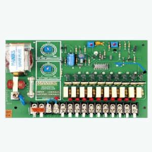
The Maniks Sequential Controller has been designed to operate the Maniks pilot valves used on dust collector Equipment.Light emitting diodes (LEDs) provide visual indication of which pilot valve is being energized as well as "Power On" indication. The number of sequenced steps is adjustable from 2 through 10.Controls are provided to adjust the length of time between valves being de-energized (Pulse Frequency / Off time) and the length of time that the valve is energized (Pulse Duration / On time). Silicon semiconductor components control all timing and logic Functions.

Two independent methods of starting and stopping the Controller are provided. The first method will automatically stop the sequence and reset the Controller to the first valve position whenever A. C. power is removed and then reconnected.

The second method is by a remote control contact connected to the terminals provided. When the remote contact is opened, the sequence stops. When the remote contact is reclosed, the sequence continues from the previous

Solid State Sequential Controller Operation:

The catalog SQP-1 Sequential Controller provides timed sequential energization of connected loads. When power is applied to the Controller, the "Power On" light emitting diode (LED) provides visual indication and pilot valve number 1 is immediately energized. "Output 1" LED provides visual indication of this event.

The pilot valve will remain energized for the length of time as indicated by the setting of the "Pulse Duration / On time" control. Note that the calibrated dials are for approximate settings only and if exact times are required, they must be measured.

Pilot valve number 2 will automatically be energized at some time interval after pilot valve number 1 has been de-energized. This length of time will be as indicated by the setting of the "Pulse Frequency / Off time" control, "Output 2” LED will provide visual indication that this event is occurring. The Controller will continue to sequentially energize the pilot valves until the power is removed.

Additional Parameters for feedback type as follows :

  • A] 1) System Ok / Timer Healthy - Potential free 'NO' relay contact.
  •      2) Sequence 'ON' / D.P. Low - Potential free 'NO' relay contact.
  • B] 1) Auto Mode - Channels activated in sequence as per 'On' and 'Off' time.
  •     2) Manual mode - Output channels are activated by pressing push button on PCB near Auto /Manual switch channel in sequence
wiring_digram

Solid State Sequential Controller Specifications:

  • A]
    Supply Voltage Input Fuse
    230VAC 1.5A
    24VDC 3A
    110VAC 3A
  • B] Pulse Frequency / Range Adjustability : Standard : 2 to 60 seconds      Special Requirements : 1) 4 to 120 seconds     2) 6 to 180 seconds
  • C] Pulse Duration / Range Adjustability : 20 to 200 milliseconds      Special Requirements : 1) 40 to 400 milliseconds     2) 100 to 1000 milliseconds
  • D] Number of Sequence Steps 2 through 10, adjustable in field (Factory set at 10) 2 through 18, adjustable in field (Factory set at 18) 2 through 40, adjustable in field (Factory set at 40)
  • E] Operating Temperature Range : 00C to 500C
  • F] Repetitive Accuracy on Time Sequence : ± 5%
  • GCurrent Rating per Sequence Step:
    Voltage Max Inrush Current Constant Current
    230 VAC 4 Amp. (50 Hz.) 2 Amp. (50 Hz.)
    110 VAC 4 Amp. (50 Hz.) 2 Amp. (50 Hz.)
  • H] Special Requirements for Voltages ( DC Kit Type ) : Following variations can be given in 10 channel, 18 channel , 40 Channel as well as with FEEDBACK Types.
    Input Voltage Output Voltage
    230 VAC 24VDC
    110 VAC 24VDC
    230 VAC 110VAC
    (NOTE: Solid-state elements require that minimum continuous current per sequence step must not be less than 0.050 amperes. Consult Factory for special rating requirements including operation below 0.050 amperes )
  • I] Consult Factory for mounting details. specification-1
ORDERING INFORMATION

Our Cat. No. : SQP - 1 for PCB & SQP - EN2 for enclosure with window. Please specify input & output voltage while ordering .

Micro Controller Based Bag Filter Timer:
microcontroller bag filter timer

What Is Maniks Micro Controller Based Bag Filter Timer:

The MANIKS Controllers of this series are micro controller based units which can be programmed to suit clients actual requirements. There are two basic modes of operation : a)Program Mode b)Manual Mode

In "program Mode" the unit can be programmed to follow desired set of instructions and in “Manual Mode “we can operate out put ( Pilot Valves ) sequentially. This controller has been designed to operate the pulse solenoid valves used on dust collector equipments.

The controller has been provided with SEEPROM to retain programmed values of various parameters in case of power failure. The programmed values automatically get stored in SEEPROM. This SEEPROM will last up to 1million read/write operations and the stored data will be retained up to many years.

Operation of Micro Controller Based Bag Filter Timer:

The Micro Controller provides timed sequential energization of connected loads. When power is applied to the controller, pilot valve will remain energized for the length of time as indicated by the setting of the “ON”control.

By keeping MENU key on key board pressed for approx 3 Sec.We can select “PROGRAM MODE” for modification in values of various parameters.

Specifications of Micro Controller Based Bag Filter Timer:

  • A
    Supply Voltage Input Fuse
    230VAC 300m A.
    110VAC 300m A.
  • B Coil Voltage: 230VAC / 110 VAC
  • C Number of Channels : 8, 16, 32
  • D On Time : 1m.Sec to 9999m.Sec.
  • D Off Time : 1m.Sec to 9999m.Sec.
  • D Pause Time : 1m.Sec to 9999m.Sec.
  • specification-2
  • G Inter Locks :(Potential Free Contacts) a) PLC can be bypassed by keeping terminals shorted / In program by selecting "NO" b) LO- Pre ( LOW-Pressure ) can be bypassed by keeping terminals shorted / In program by selecting "NO" c) HP- Pre ( High-Pressure )
  • H Feed Back Provided : Potential Free "NO" Contacts A) Pulsing On A) Timer On
  • I Enclosure - SIEMENS GRAY Powder coated Canopy Type (equivalent to IP 55 )
  • J Display - LCD Display
  • K Mountings - Consult Factory for Mounting display
  • L Special Requirements for Voltages Following variations can be given in 8 channel,16channel,32 channel
    Input Voltage Output Voltage
    230VAC 24 VDC
    110 VAC 24 VDC
    NOTE: Solid-state elements require that minimum continuous current per sequence step must not be less than 0.050 amperes. Consult Factory for special rating requirements including operation below 0.050 amperes)
  • specification-3
ORDERING INFORMATION :

Our Cat. No. : MSQP - 1 for PCB & MSQP - EN2 for enclosure with window. Please specify input & output voltage while ordering .

Special Services
maniks repair kit
  • We offer special service for your existing system components for pneumatic pulse application, to recondition your inoperative valves and assure operating reliability as good as new . DO NOT scrap your valves (ONLY IMPORTED) unless inspected by our experts.
  • We offer SPARE DIAPHRAGMS , PILOT SOLENOIDS and COILS for your EXISTING IMPORTED VALVES.
  • We provide special enclosures for timers such as flame proof enclosures , SS enclosures , FRP enclosures , IP65 enclosures on request.
  • We also cater to special requirement such as flame proof enclosures for valves.